Source Rebuild and Filament Replacement
Overview
This document is to cover the servicing and maintenance of the isoprime visION Mass Spectrometer source assembly from system shut-down to setting the correct alignment for the filament.
The filament position is fixed but the trained user must follow some simple steps to guarantee the filament is always fitted in a repeatable position on all axis.
System Venting
Venting the system via IonOS is initialized by selecting the Control button on the ribbon under the Layout tab.
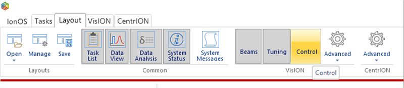
Figure 8-1: IonOS Connected System Ribbon Tab - Opening the Control Panel
The following window will open with the pumping control for both the Turbo and Rotary pumps being shown and. Depending on how the layout was last saved when IonOS was closed then you may have to resize the window for improved usability.
It is recommended that the source and magnet are turned off before venting the system
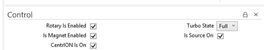
Figure 8-2: Control Panel
Uncheck the “Is Magnet Enabled” and “Is Source On” to turn off both the magnet and source
Also, via the drop-down menu, set the “Turbo State” to Off. This will remove the supply voltage to the turbo and cause it to slow and then vent once the speed falls below 50% or 500 on the system status window
If you have a manual Isolation Valve, set the Isolation Valve to “Closed” by turning the valve control fully clockwise. This will isolate the turbo from the rotary pump.
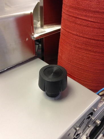
Figure 8-3: Manual Isolation Valve
The rotary can now be shut down (software control via the MPSU) be deselecting the “Rotary Is Enabled” checkbox within the control panel.
The following message will be displayed within the System Status window once all the above steps have been completed.
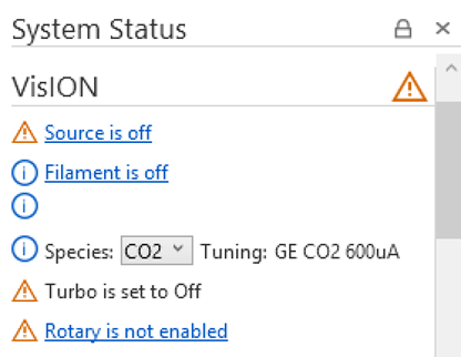
Figure 8-4: isoprime visION System Status after venting procedure has been followed
Wait for the turbo speed to fall below 50% and the system should be heard to vent. This process will take a couple of minutes for the turbo to stop fully and the vacuum to reach atmospheric pressure. Once the Low Vacuum gauge reaches ~1013mBar the source flange may be removed to reveal the source.
Source Flange Removal
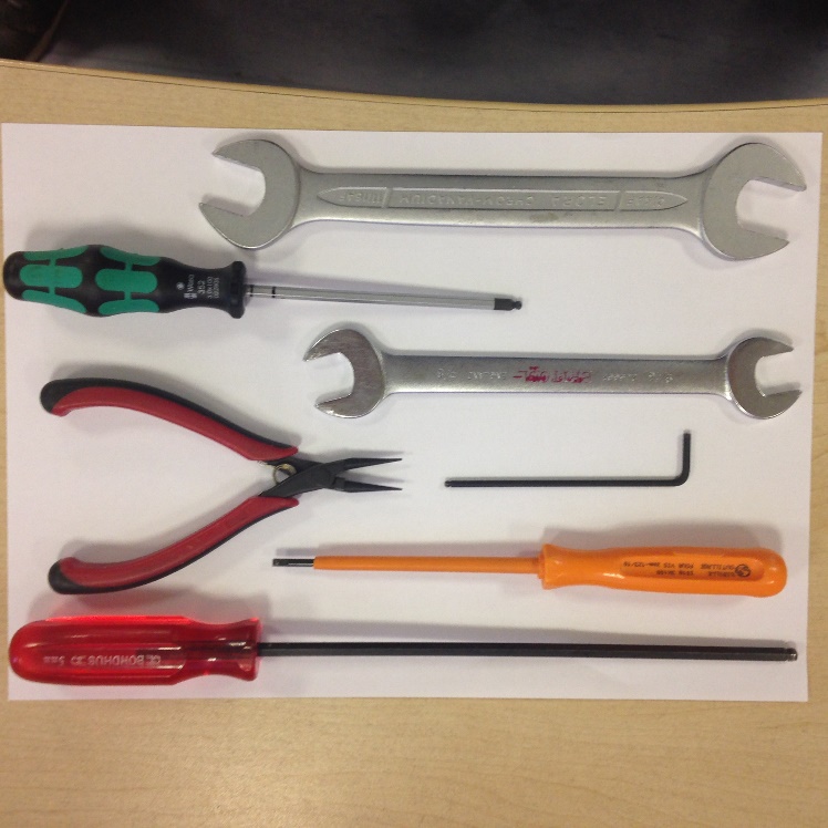
Figure 8-5: Tools required to remove source flange
To remove and service the source you will need the following tools:
- ¾” spanner
- 4mm Allen Key
- 5/8” spanner
- Thin-nosed pliers
- 2.5mm Allen Key
- 3mm screw driver
- 5mm Allen Key
All tools should be cleaned before usage to prevent contamination when servicing the source
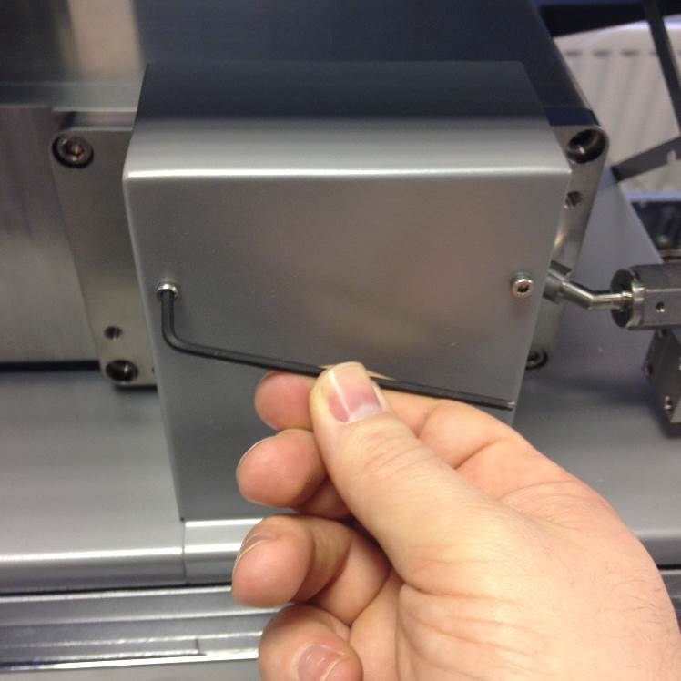
Figure 8-6: Removing the source cover
Open the lid to the isoprime visION Mass Spectrometer to reveal the source cover. Using a 2.5mm Allen Key remove the two fastening screws.
Removal of the source cover will break the interlocks which control the output of the source power supplies.
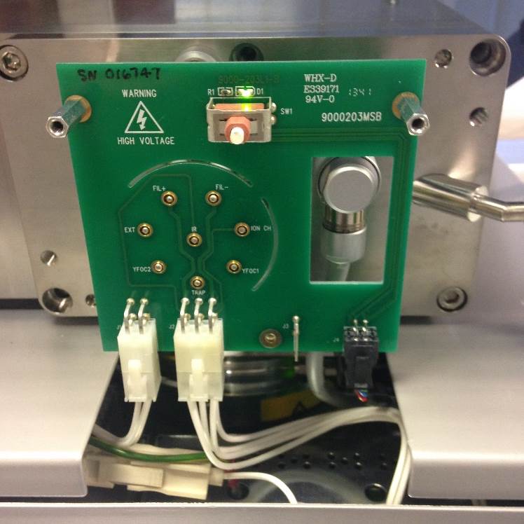
Figure 8-7: Source with source cover removed
Once the cover is removed the Source Feedthrough PCB will be visible. The illuminated green LED status will show that the interlocks have been broken. The interlock connection is the 4-way black microfit and will have a 24V supply.
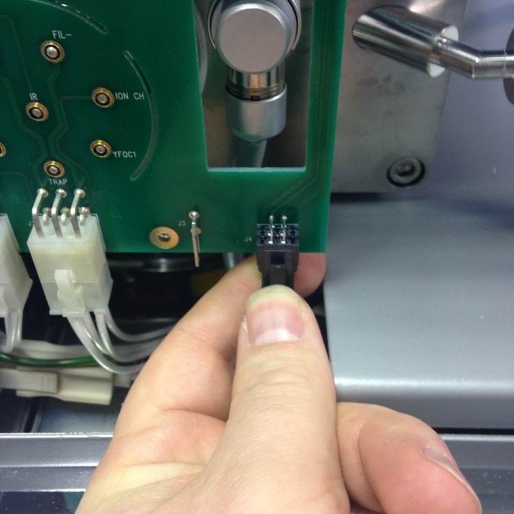
Figure 8-8: Source interlock connection
Remove the interlock connection and the PCB will have no voltage (HV or LV applied)
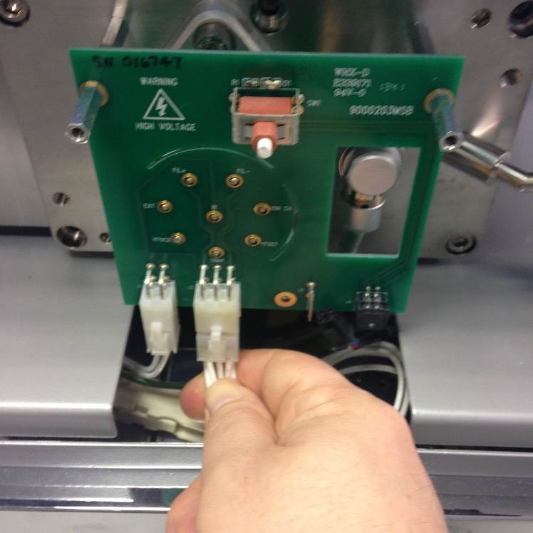
Figure 8-9: Source connectors (6-way)
Remove the 6-way and 4-way source connections
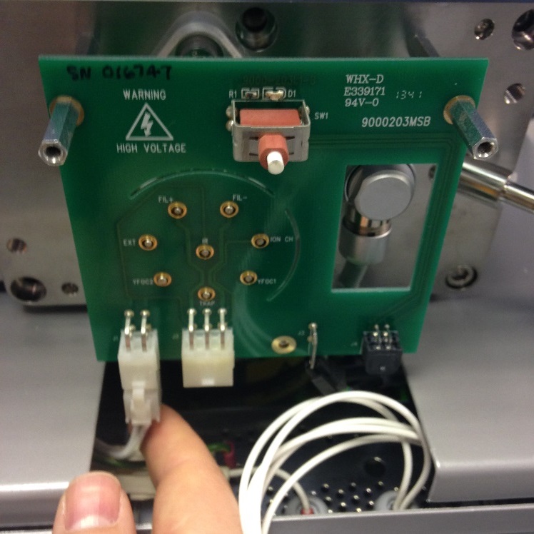
Figure 8-10: Source connectors (4-way)
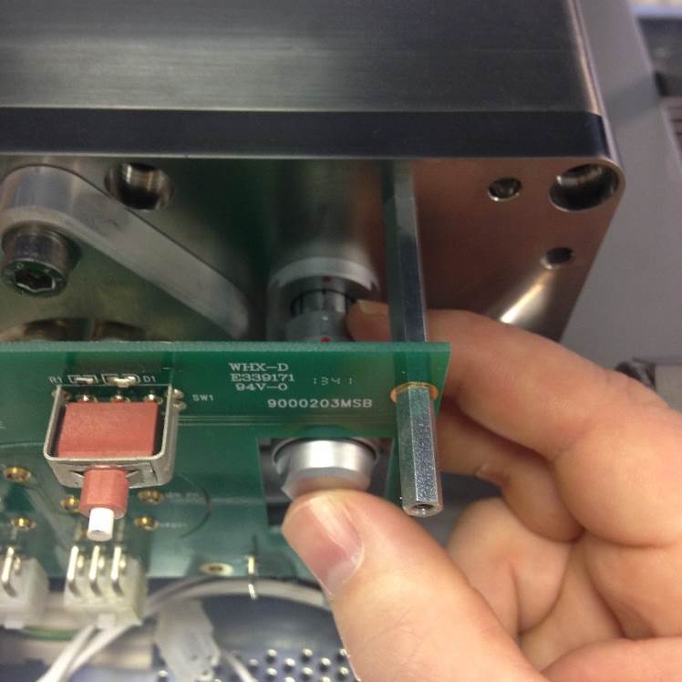
Figure 8-11: Source Z-Plate Connection
Remove the ZP connection
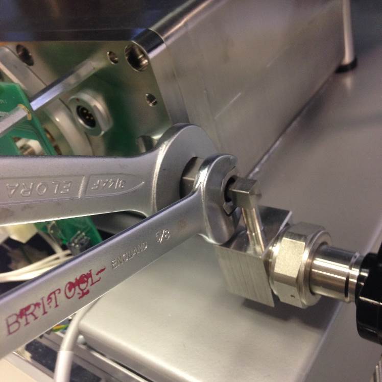
Figure 8-12: Undoing the VCR connection
Undo the VCR connection with the ¾” and 5/8” spanner
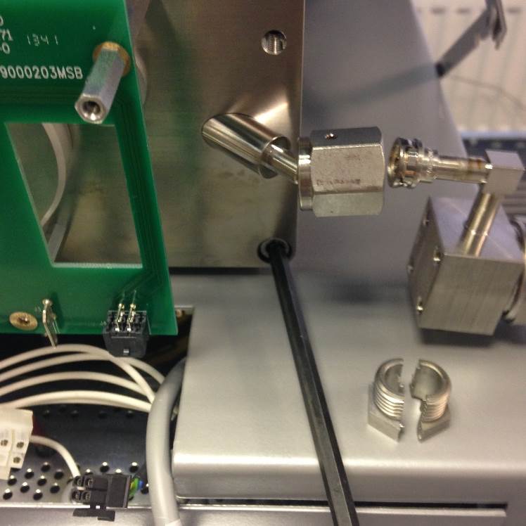
Figure 8-13: Nupro valve - split nut
The Nupro valve has a split nut which can be fully removed. The VCR gasket will be fitted to the Nupro side of the seal.
Undo the M6 screws (5mm Allen Key, x6) to release the source flange
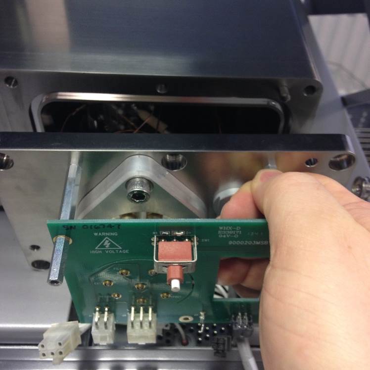
Figure 8-14: Removing the source flange from the vacuum housing
The flange can now be removed from the vacuum housing.
Be careful not to damage the source or sealing ring during the removal.
Source Removal
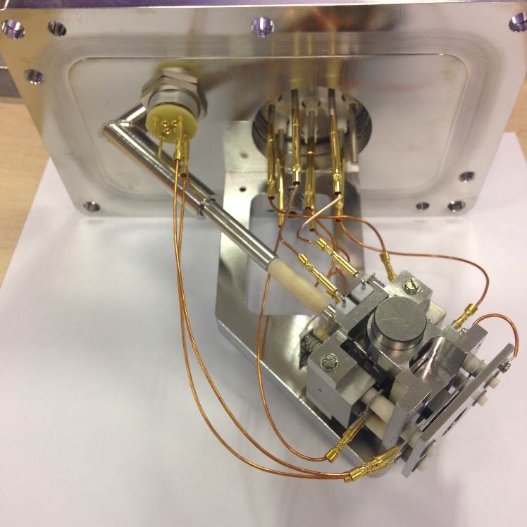
Figure 8-15: [Source and Flange Assembly]
The internal transfer line is via a fixed length of pipe welded to the source flange and a 3-section sprung insulated section.
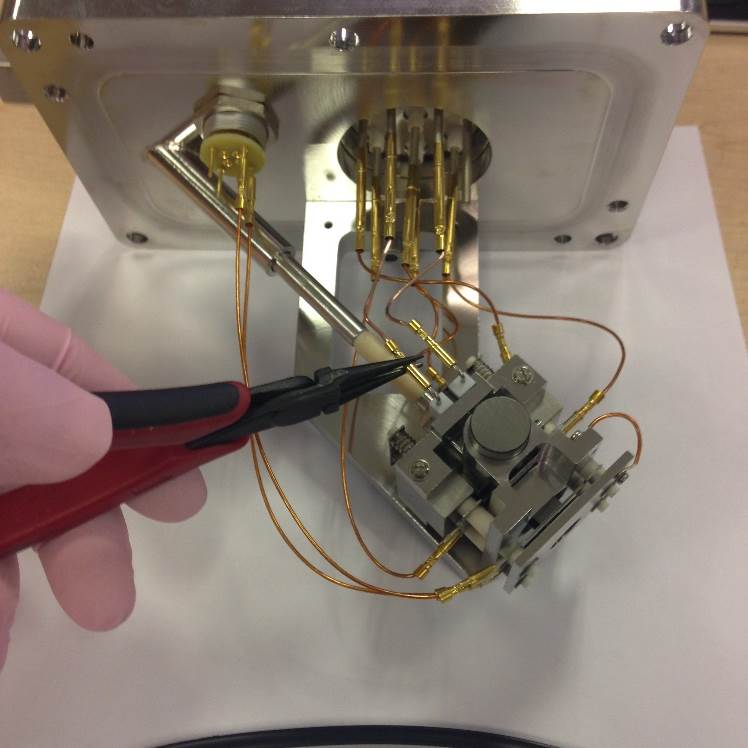
Figure 8-16: [Remove Filament Wires]
Remove the source wiring using the cleaned thin-nosed pliers.
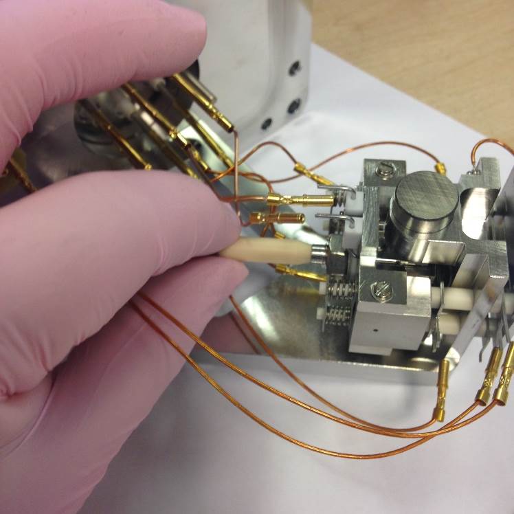
Figure 8-17: [Remove Tapered Inlet Tube]
To remove the gas transfer pull the ceramic isolator away from the source. Keeping the spring compressed, move the ceramic away from the assembly. You will then be able to remove both the stainless steel pipe and the spring which sits within the fixed section.
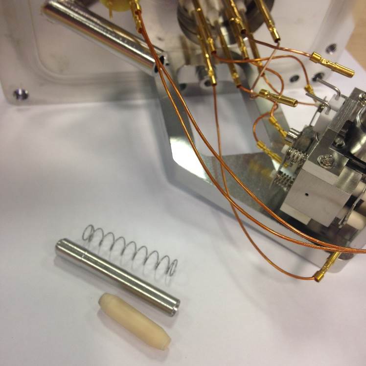
Figure 8-18: [Inlet Tube, Inlet Tube Holder and Compression Spring]
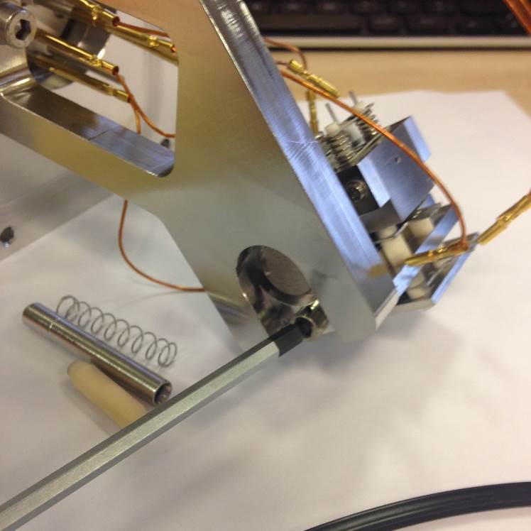
Figure 8-19: [Unscrew Source Fixing Screw]
Tilt the source flange and undo the M4 Allen Screw.
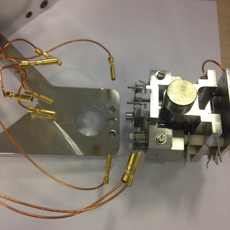
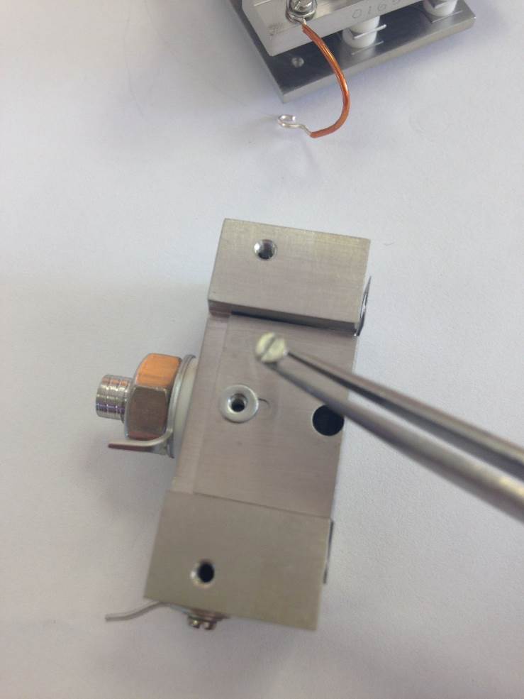
Figure 8-20: [Figure Description]
The source can then be removed fully from the flange assembly.
Source wiring
The source connections are wired internally as shown in the following diagrams.
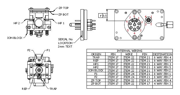
Figure 8-21: [Source Wiring Positions]
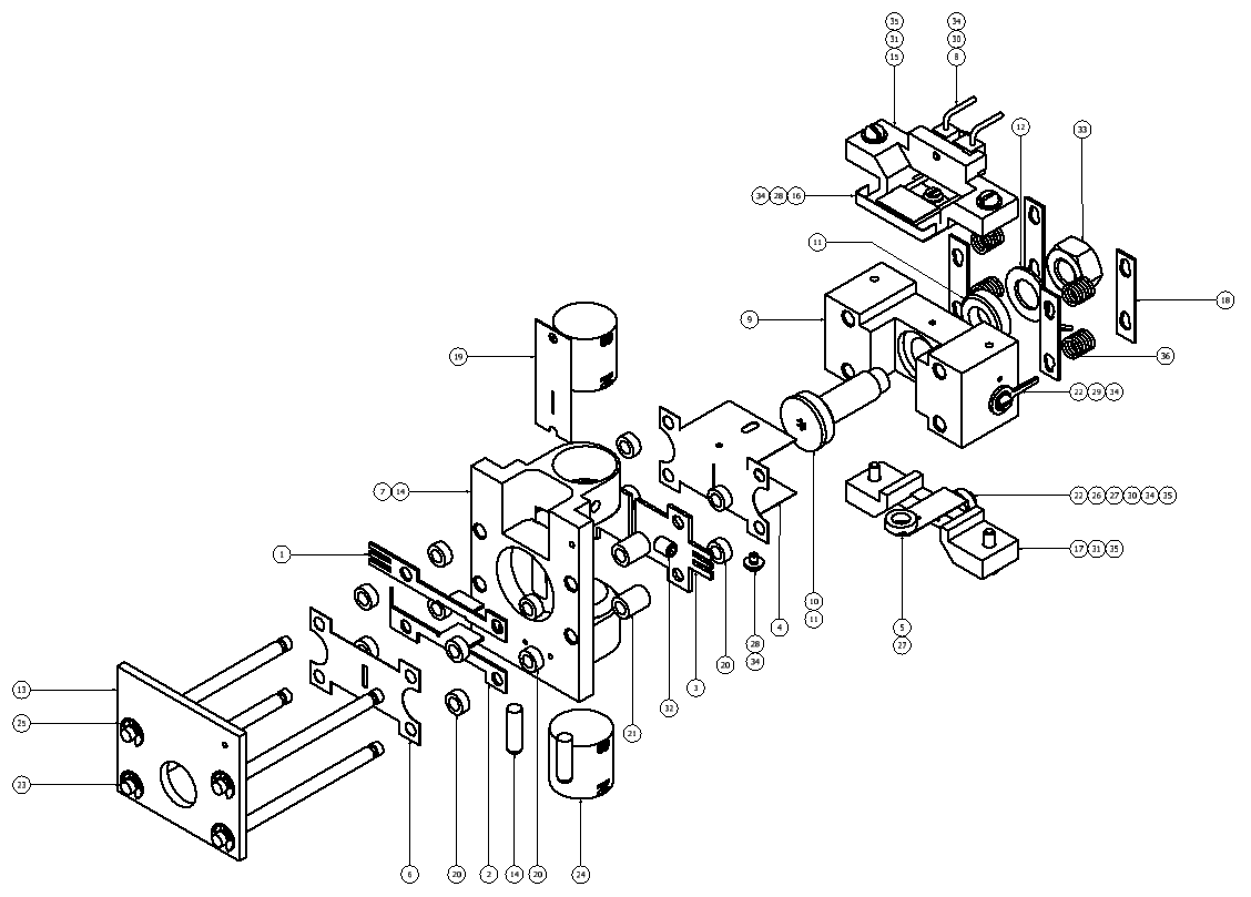
Exploded Diagram
|
ITEM |
QTY |
PART NUMBER |
DESCRIPTION |
|---|---|---|---|
|
1 |
1 |
M693023BD1 |
PLATE Z UPPER |
|
2 |
1 |
M693024BD1 |
PLATE Z LOWER |
|
3 |
2 |
M693029CD1 |
PLATE HALF |
|
4 |
1 |
M693030CD1 |
PLATE ION EXIT SLIT 5MM |
|
5 |
1 |
M900076BD1 |
TRAP DETAIL |
|
6 |
1 |
T3009880 |
ALPHA PLATE |
|
7 |
2 |
M693073AD1 |
POLE SHOE TYPE 1 |
|
8 |
1 |
M693285BC1 |
FILAMENT ASSY |
|
9 |
1 |
M900021CD1 |
ION BLOCK REAR CENTRE INLET |
|
10 |
1 |
M900022AD1 |
ION REPELLOR WITH GAS INLET |
|
11 |
2 |
M900023AD1 |
CERAMIC SPACER - ION REPELLOR |
|
12 |
1 |
M900024AD1 |
TERMINAL WASHER 6MM ID |
|
13 |
1 |
M900028BD1 |
END PLATE |
|
14 |
1 |
M900029AC1 |
ASSEMBLY SLIT-MAGNET SUPPORT |
|
15 |
1 |
M900071CD1 |
FILAMENT SUPPORT |
|
16 |
1 |
M900072BD1 |
ELECTRON ENTRY PLATE |
|
17 |
1 |
M900073CD1 |
TRAP SUPPORT |
|
18 |
4 |
M900074AD1 |
LOCKING PLATE |
|
19 |
1 |
M900075AD1 |
DEFINING SLIT |
|
20 |
12 |
STD0006AD3 |
CERAMIC SPACER (2MM) |
|
21 |
4 |
STD0006AD9 |
CERAMIC SPACER (6MM) |
|
22 |
2 |
STD0007AD1 |
TERMINAL WASHER |
|
23 |
4 |
STD0008AD1 |
CERAMIC ROD (45MM) |
|
24 |
2 |
STD0009AD1 |
MAGNET DETAIL |
|
25 |
4 |
T1026022 |
CIRCLIP |
|
26 |
1 |
T1640016 |
CERAMIC SLEEVE 3.5MM |
|
27 |
3 |
T1640052 |
SPACER CERAMIC 0.071IN |
|
28 |
2 |
5311037 |
SCREW CSK M1.6 X 3 LG ST STL |
|
29 |
1 |
5314041 |
SCREW M1.6 x 3 CH SLT A4 SS |
|
30 |
2 |
5314044 |
SCREW M1.6 x 8 CH SLT A4 SS |
|
31 |
4 |
5314065 |
SCREW M2 x 8 CH SLT A4 SS |
|
32 |
2 |
5316005 |
SCREW M3 X 4 SKT SET A4 SS |
|
33 |
1 |
5321007 |
NUT M6 FULL A4 SS |
|
34 |
5 |
5331013 |
WASHER M1.6 FLAT A4 SS |
|
35 |
5 |
5331014 |
WASHER M2 FLAT A4 SS |
|
36 |
4 |
06 00 0448 |
COMPRESSION SPRING |
Figure 8-22: [Source Exploded Diagram]
Source Assembly
The source should always be assembled using a source assembly jig. This will prevent any metal lens from being drawn along the ceramic rods and thus reducing the possibility of breakdown via surface contamination.
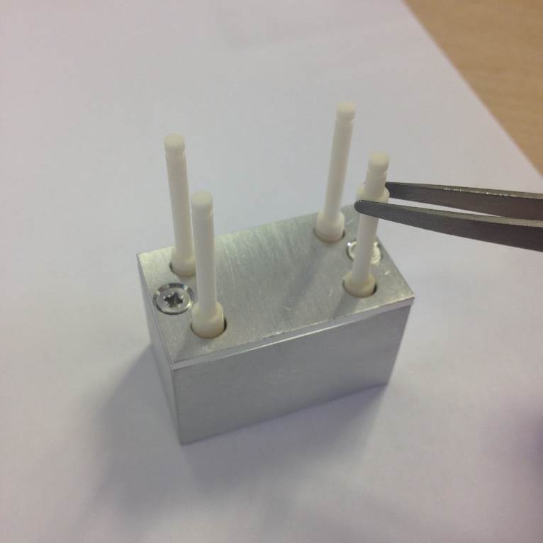
Figure 8-23: [Source Assembly Jig with Ceramic Rod and Ceramic Spacer (2mm)]
Slide the 4 Ceramic Rods into the location holes in the source jig.
Then fit the 4 Ceramic Spacers (2.0 MM).
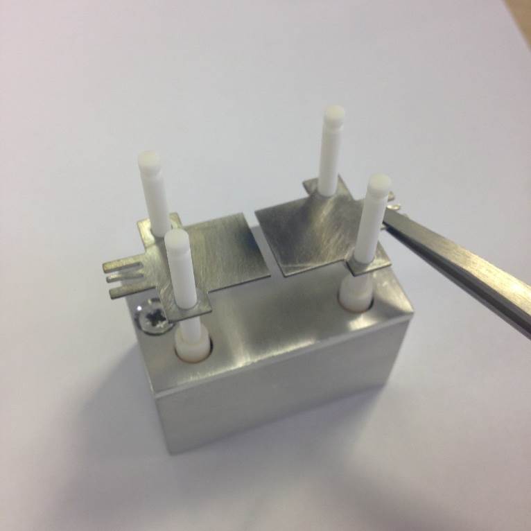
Figure 8-24: [Half Plates Fitting]
Fit the Half Plates on to the Ceramic Rods.
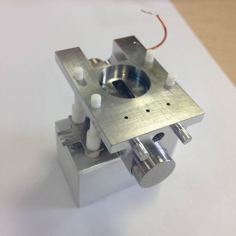
Figure 8-25: [Assembly Slit-Magnet Support]
Fit the 4 Ceramic Spacers, 6.0 MM, and the Assembly Slit-Magnet Support with additional fittings (magnet poles, defining slit etc.).
Note the magnet orientation. North “N” should be in the lower position for both source magnets once the source is fitted to the flange.
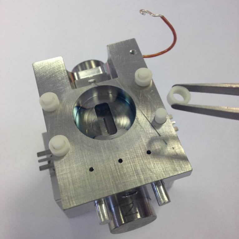
Figure 8-26: [Ceramic Spacer Fitting - Slit-Mganet Support to Z Plates (ZP)]
Fit the 4 Ceramic Spacers (2.0 MM).
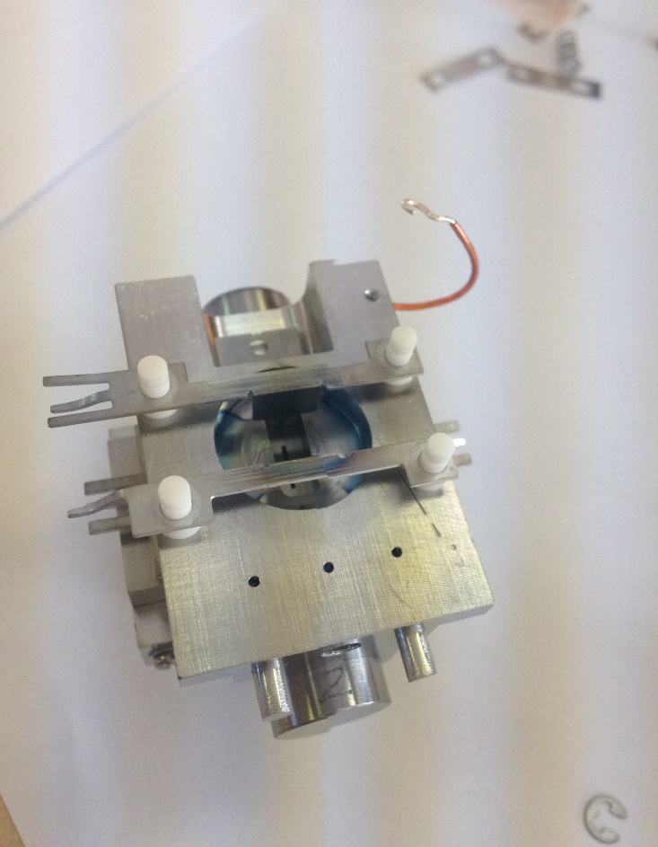
Figure 8-27: [Plate Z Upper and Lower (ZP)]
Fit the Plate Z Upper and Plate Z Lower. The lower plate is mounted closer to the location dowels.
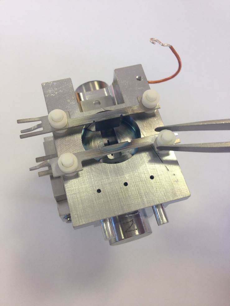
Figure 8-28: [Ceramic Spacers (2.0 mm), ZP to Alpha Plate]
Fit the 4 Ceramic Spacers ( 2.0 mm).
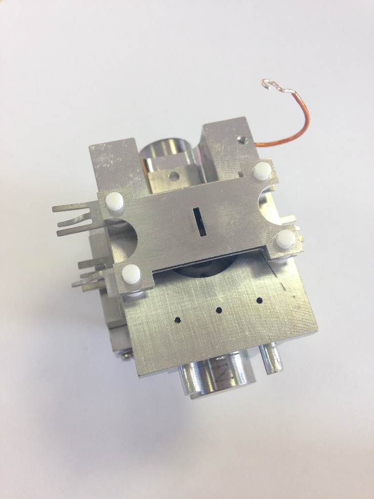
Figure 8-29: [Alpha Plate]
Fit the Alpha Plate
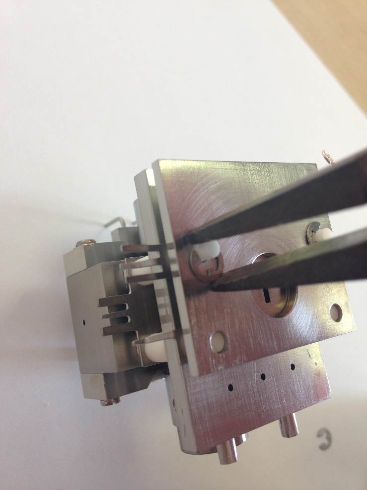
Figure 8-30: [Circlip Locks]
Fit the End Plate (Source) and the 4 Circlips.
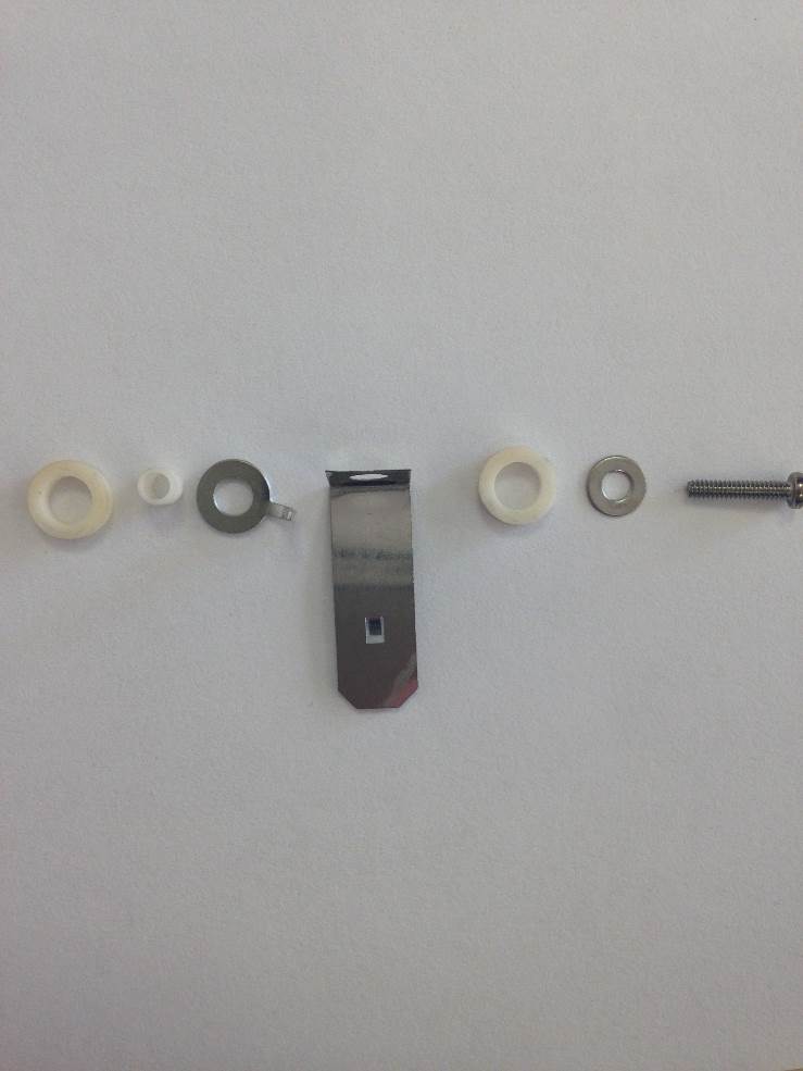
Figure 8-31: [Trap Assembly]
The trap assembly is awkward to assemble, so please have the correct size tool on hand. Tweezers and 3mm screwdriver are recommend.
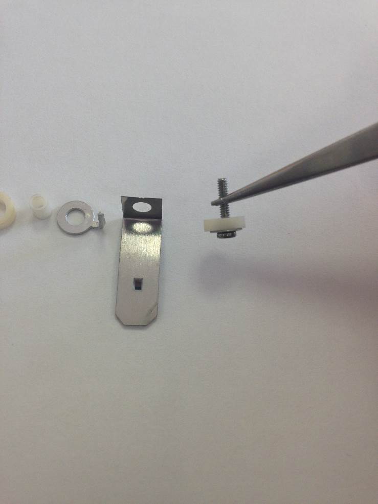
Figure 8-32: [Trap mounting screw with isolation ceramic]
Take the M1.6 screw and and slide the M1.6, M2* and Ceramic Washer over. *M2 Washer not shown.
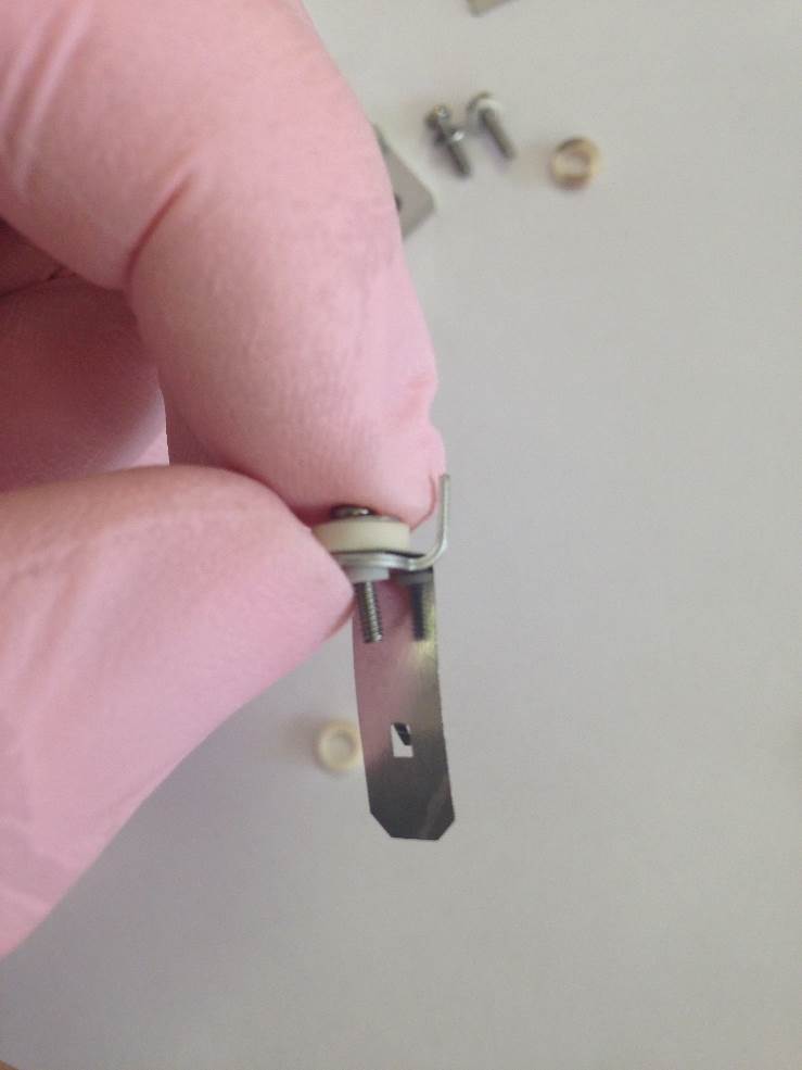
Figure 8-33: [Ceramic Sleeve, Trap Detail and Terminal Washer]
Slide the Ceramic Sleeve, Trap Detail and Terminal Washer over the screw.
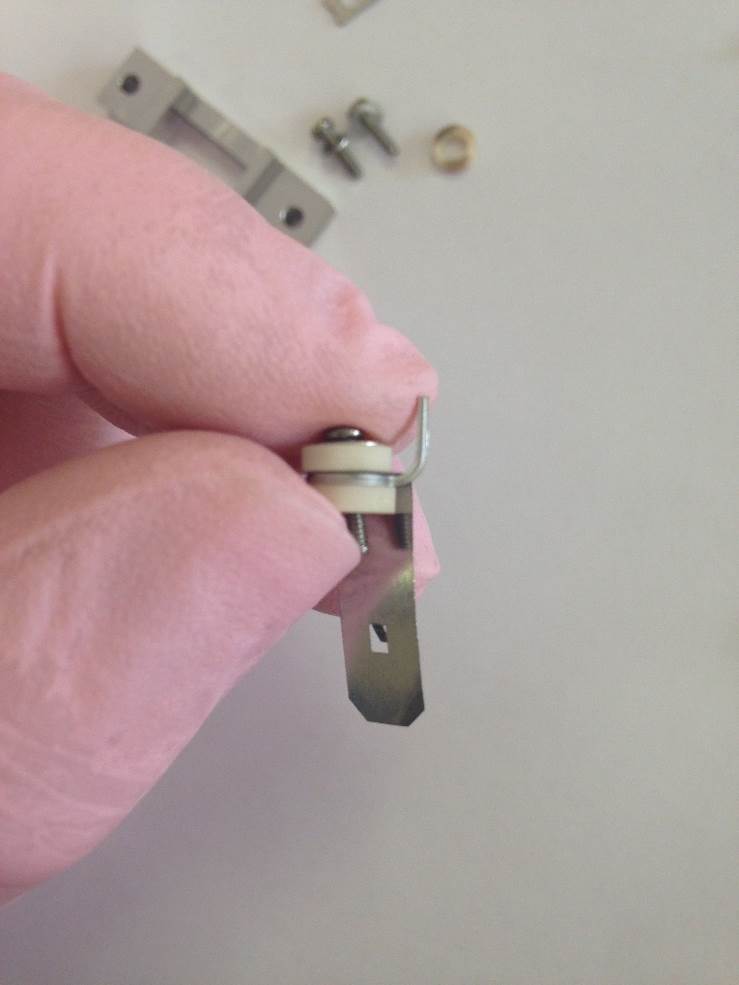
Figure 8-34: [Second Spacer Ceramic]
Then slide the second Ceramic Spacer over the screw.
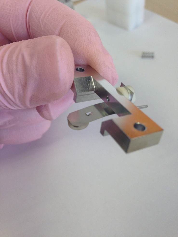
Figure 8-35: ['Trap Assembly' fitted to Trap Support]
Fit the trap assembly on to the Trap Support. Another Spacer Ceramic is also fitted to the trap at the end where the electrons are incident. When correctly installed the ceramic will not fall off when facing downwards.
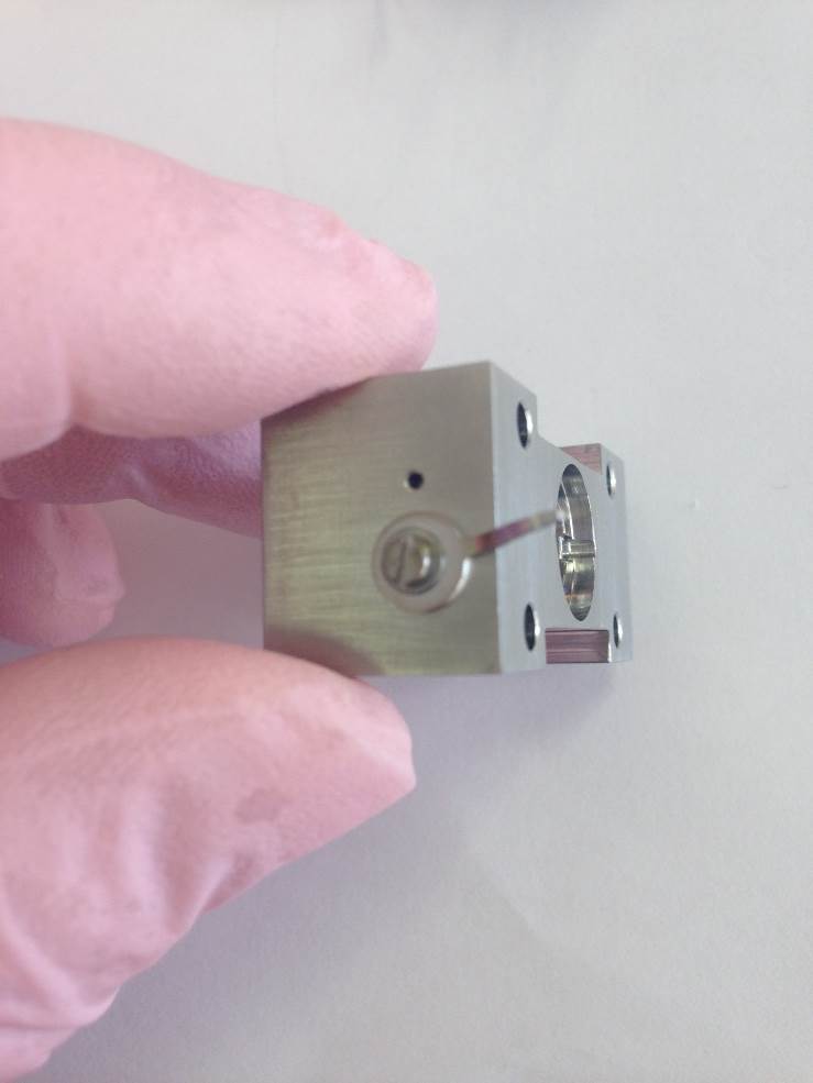
Figure 8-36: [Ion Block Terminal]
Fit the Terminal Washer, M1.6 Screw and M1.6 Washer to the side of the Ion Block.
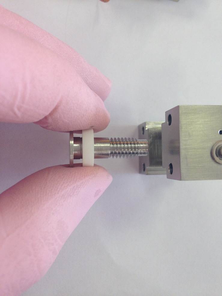
Figure 8-37: [Figure Description]
Fit the Ion Repeller and Ceramic Spacer are fitted through the ion block from the large-recess front side.
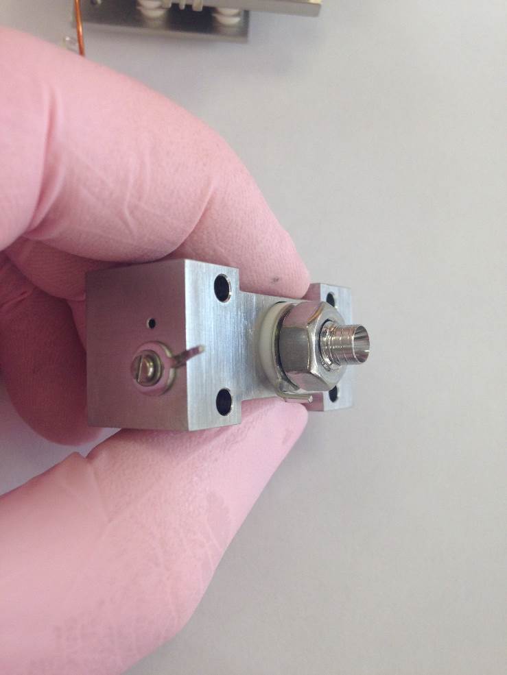
Figure 8-38: [Ion Repeller Terminal Washer and Locking Nut]
Fit the second Ceramic Spacer, Terminal Washer and Nut.
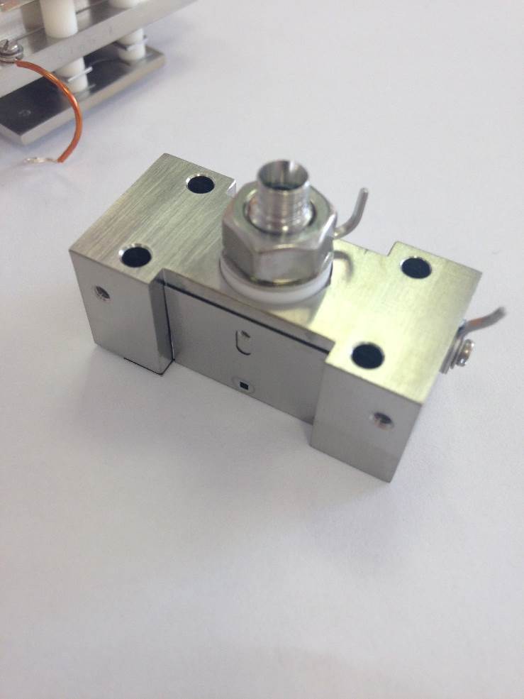
Figure 8-39: [Ion Exit Slit 5mm]
Fit the Ion Exit Slit with the square hole facing upwards toward where the filament will be located.
Secure the plate on the trap side with a M1.6 counter-sunk screw and washer.
 .
.
Figure 8-40: [Fixing the Ion Exit Slit]
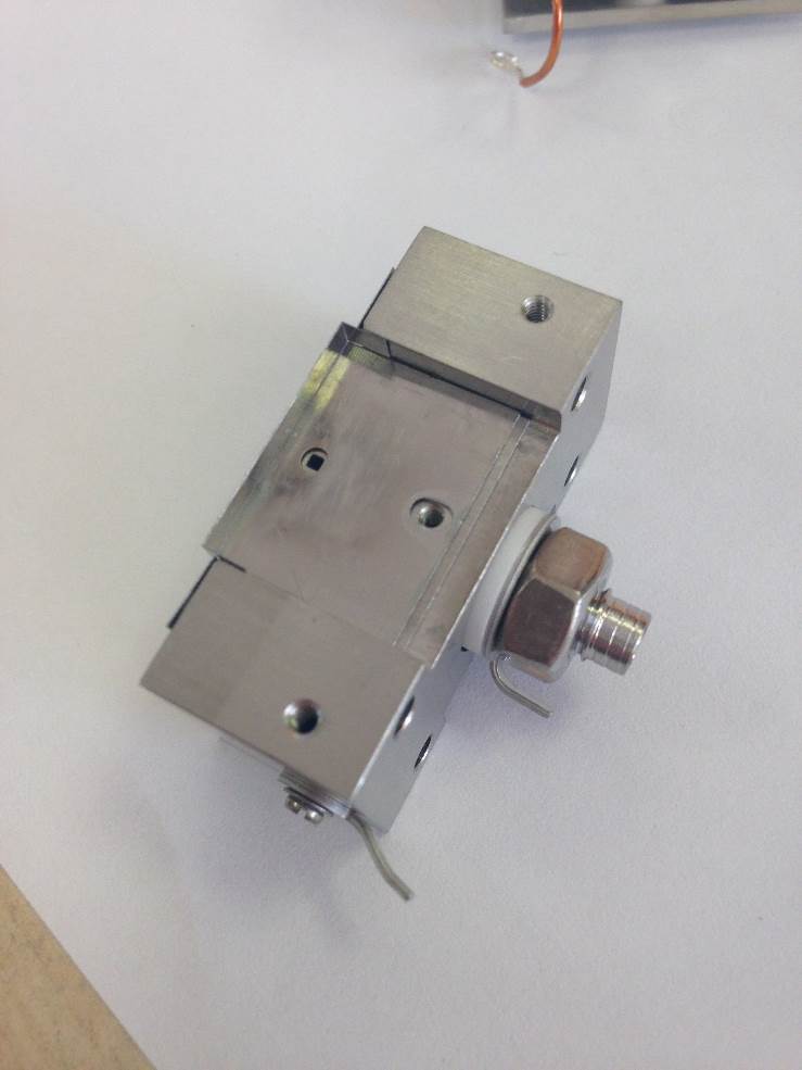
Figure 8-41: [Fixing the Electron Entry Plate]
Fit the Electron Entry Plate using another M1.6 counter-sunk screw and washer. Check that the square hole on the ion exit plate is central to the circular one on electron entry plate.
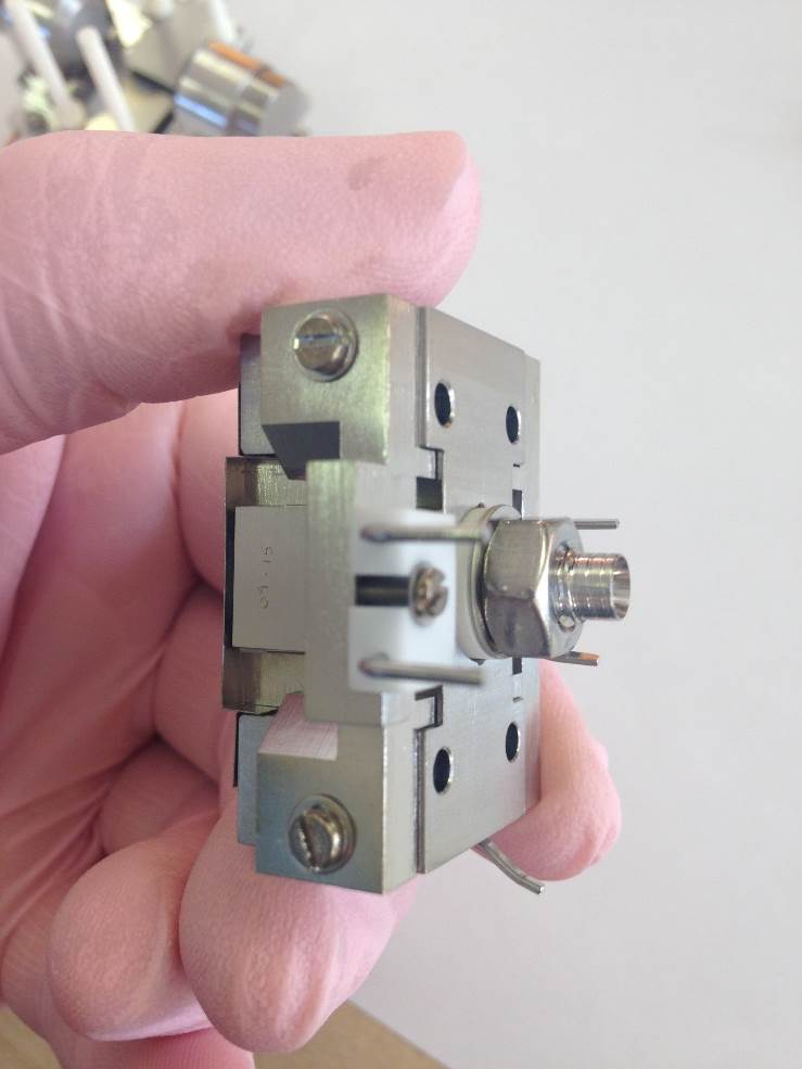
Figure 8-42: [Filament Support bracket]
Fit the Filament Support Assembly using two M2 Screws and Washers.
Do not fully tighten the screws at this point. The assembly should be able move slightly
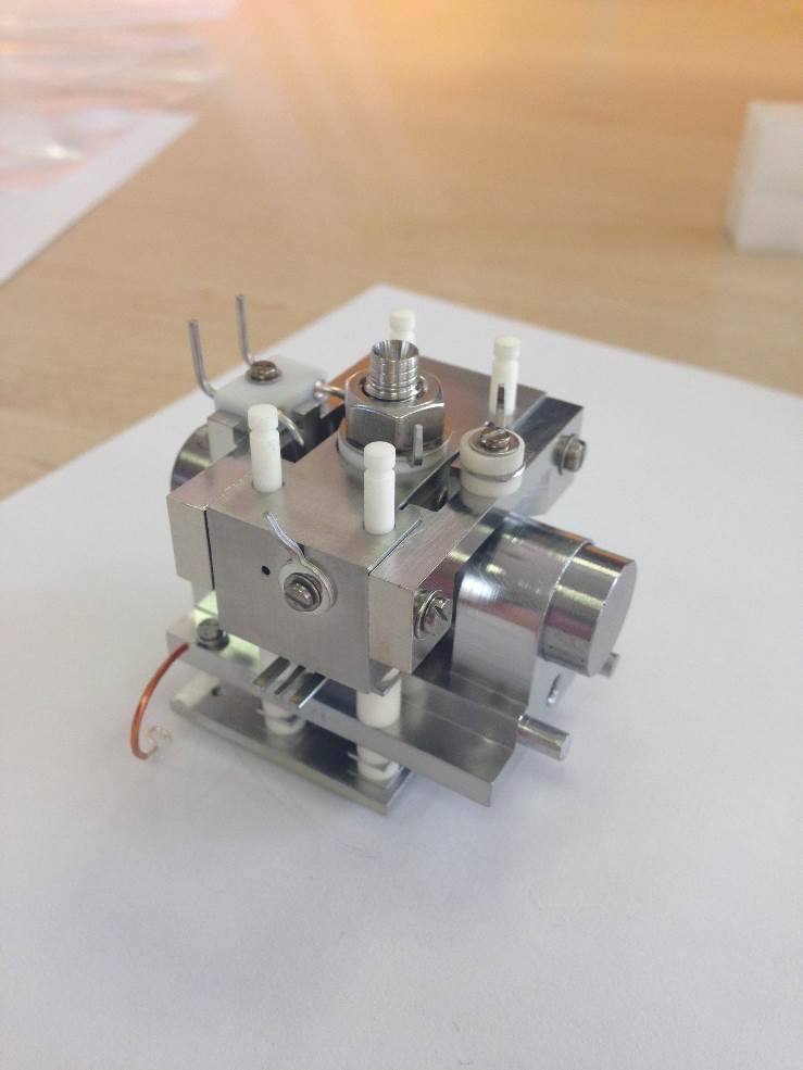
Figure 8-43: [Filament and Trap Supports]
Fit the Trap Support Assembly using the same size screws and washers.

Figure 8-44: [Locking Plates]
Fit two of the Locking Plates and the 4 Compression Springs
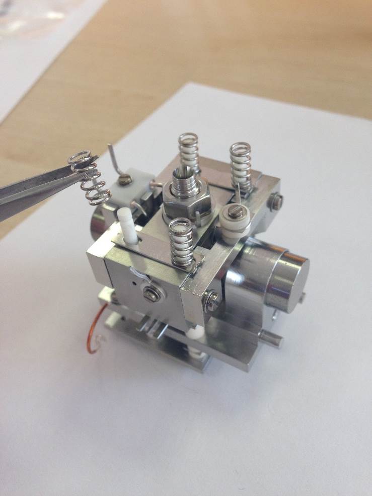
Figure 8-45: [Compression Springs]
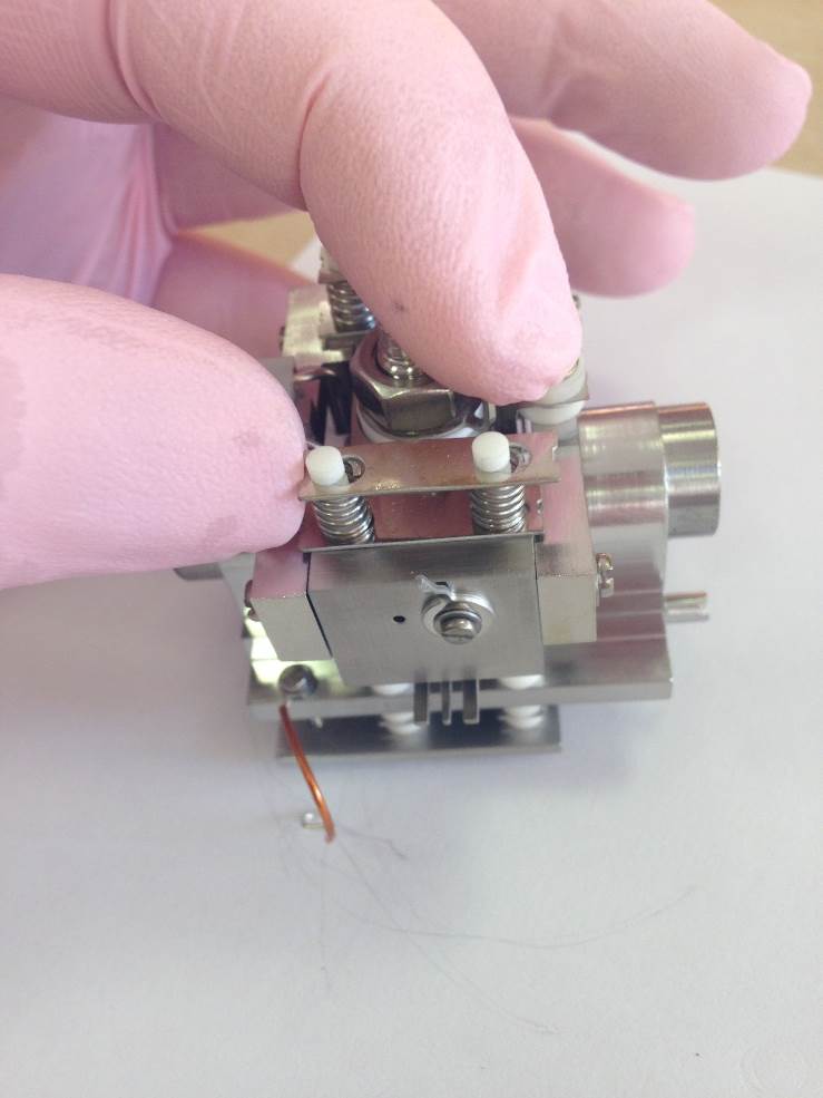
Figure 8-46: [Outer Locking Plates]
*The wearing of safety goggles is recommended for this part of the assembly.
Push the plates down on to the springs and then slide toward the smaller end of the cut-out so that they lock in place.
The source will now be fully compressed.
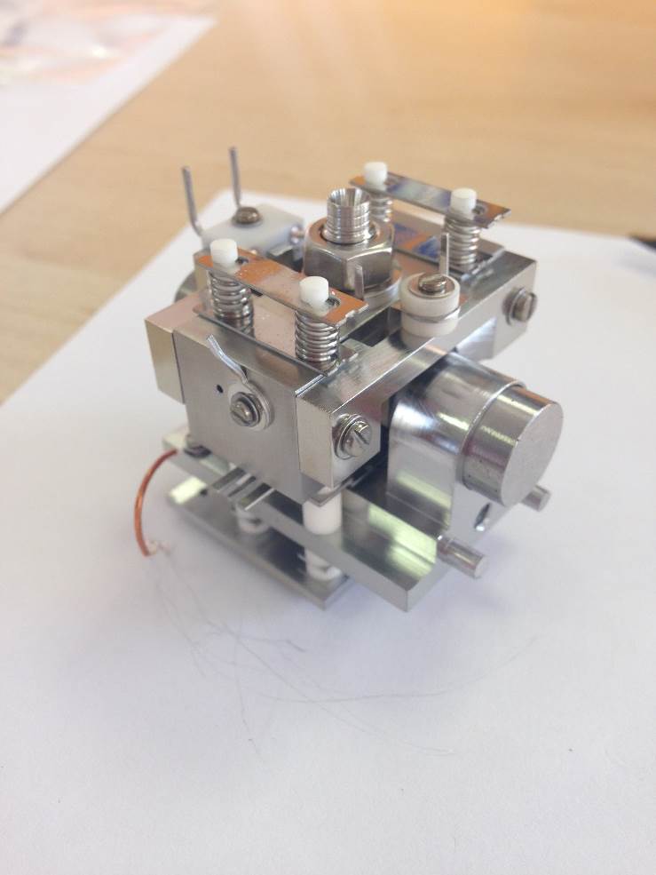
Figure 8-47: [Source Assembly locked]
Both of the support brackets should not be touching the locking plates.
Slide both support brackets so that they touch the locking plates. This will guarantee the correct alignment of the filament and the trap.
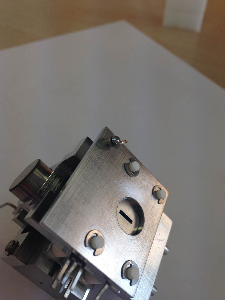
Figure 8-48: [End Plate Grounding]
Fit the M1.6 screw, washer and wire to the END PLATE.
The other end will be terminated upon the Slit-Magnet Support.
Filament alignment
To align the filament correctly the following procedure should be followed. The filament will be aligned in all 3-dimensions, in depth, centrality and height.
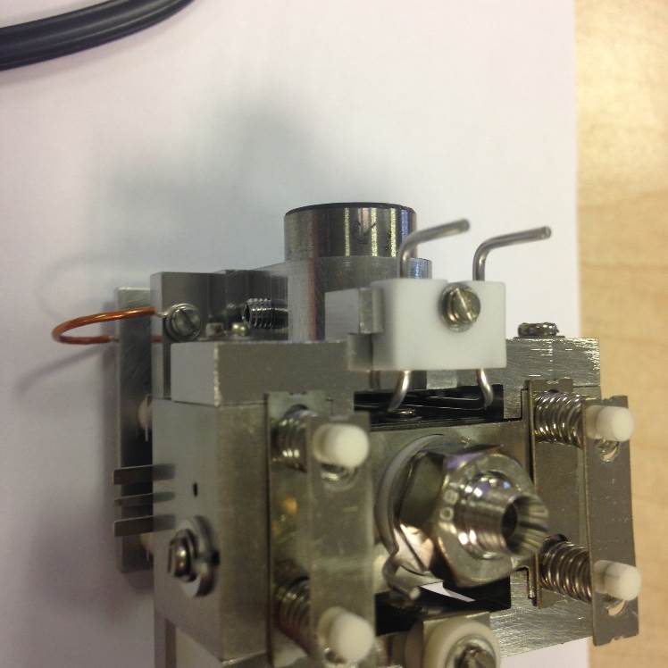
Figure 8-49: [Filament and Filament Support]
Mount the filament to the support bracket using the slotted-screw, but don’t fully tighten.
Push the filament down toward the source body and across to the left. It will then be pressed against the bottom positioning lug and also the left-hand lug. This will set the height in relation to the support bracket and the centrality of the filament wire to the ion block assembly.
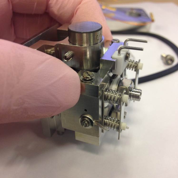
Figure 8-50: [Filament Support Alignment]
Slide the filament assembly away from the source magnets until it touches both of the locking plates.
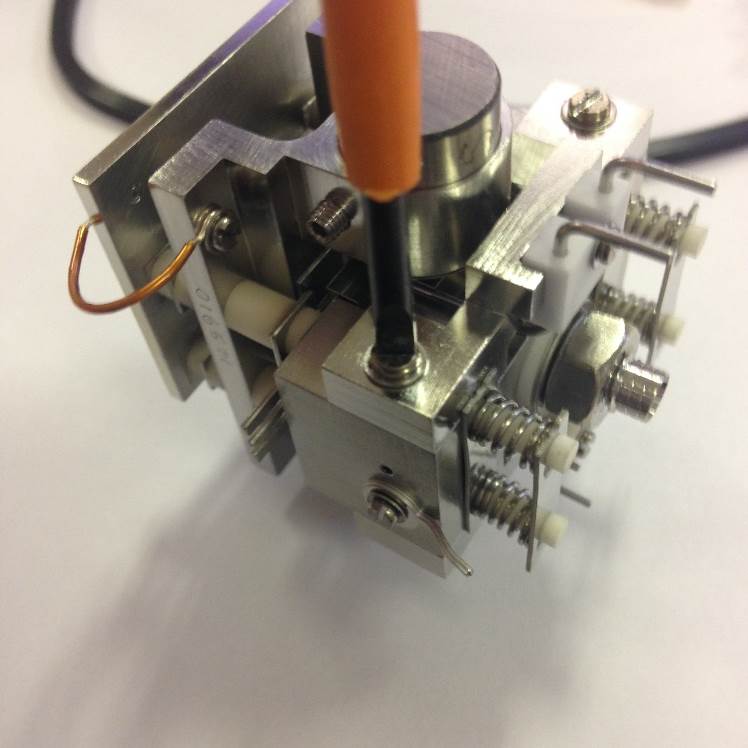
Figure 8-51: [Filament Support Fixing]
Tighten the two fixing screws. The filament will now be centrally aligned with the window of the ion block.
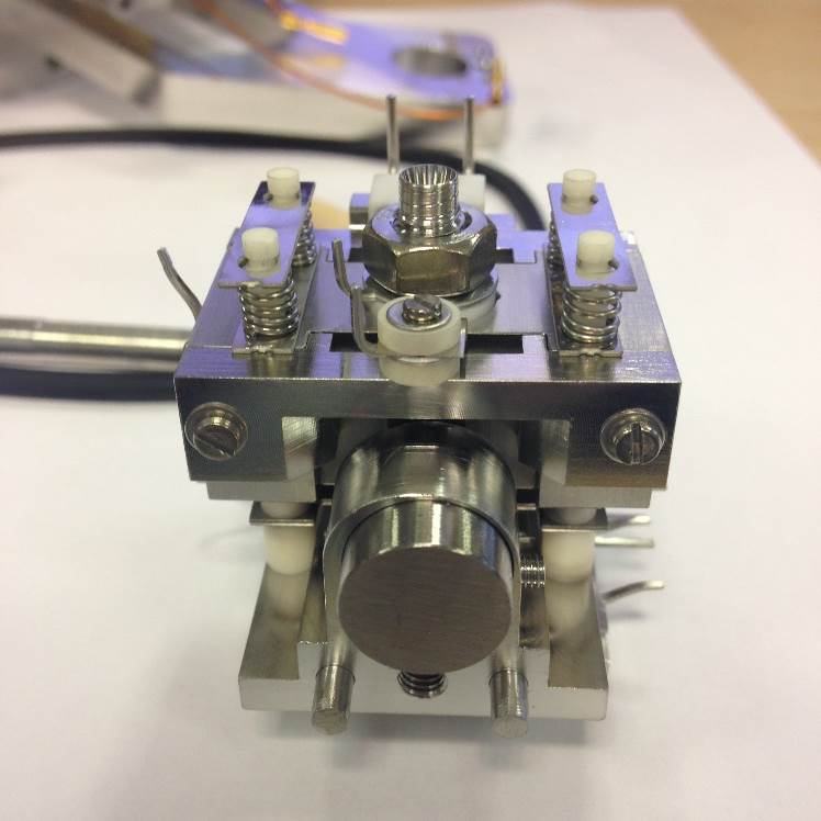
Figure 8-52: [Filament Support Alignment with Locking Plates]
Here there is no gap between the filament support bracket and the locking plates nor does the bracket over-hang the rear of the ion block.
If the rear of the filament support bracket and the rear of the ion block aren’t aligned correctly then the filament will also be misaligned.