PYRO cube, ISOTOPE cube and ISOTOPE select
For a comprehensive guide on setting up the PYRO cube, ISOTOPE cube and ISOTOPE select, please refer to the PYRO cube, ISOTOPE cube and ISOTOPE select user manual.
Installation Site Requirements
The site requirements should be met before an installation can proceed, see Site Requirements.
Installing the instrument software
In order to install the software correctly, administrator rights for the PC must be available (administrator rights are not required for normal operation of the software).
Do the following to be able to operate the software without any problems:
- On the PC where the software is installed, check power management settings under Control Panel > Power Management or under Control Panel > Power Options. The following options must be set to "Never"
- "Turn off monitor"
- "Turn off hard disks"
- "System stand by"
- "System hibernates"
- Power management must also be disabled in the PC's BIOS.
- The PC on which the software is installed must not be overloaded with other software. This could cause unstable operation of the software.
Instructions for operating the furnace
Observe the instructions for using the furnace so that the warranty is upheld.
Start-up
In order to ensure proper working order of the instrument:
- the work processes described in this section must be performed precisely.
- the basic instrument and the peripherals must be switched on in the sequence described here.
The section is divided into the following phases:
- Preparing instrument for switching on
- Preparing the Instrument for measurements
- Performing instrument checks
Phase 1: Preparing instrument for switching on
- Set up the instrument. Observe the instructions concerning the installation site.
- See Installation site requirements (within the EA manual).
- Connect the peripherals.
- See Connecting peripherals (within the EA manual).
- Connect supply lines and waste gas lines.
- See Connecting supply lines and waste gas lines (Connecting Supply / Waste Lines ).
- Remove the transport lock.
- See Removing the transport lock (within the EA manual).
Operating instructions
- Check the fillings of the required glass and quartz components. Replace filling if necessary.
- See: Emptying and filling standard reaction tubes (within the EA manual).
- See: Filling, removing and installing the absorption and drying tubes (within the EA manual).
- Install the required glass and quartz components.
The instrument is now ready for switching on.
Phase 2: Instrument must be ready to measure
Proceed as follows:
- Perform all steps of the switching on process.
- See Switching on (within the EA manual).
- Switch on the operating gases.
- See Default instrument settings (within the EA manual) for recommended gas pressure.
- Launch the operating software. The standard operating parameters are factory-set and do not have to be optimized by the user.
- See Starting the operating software (within the EA manual).
- Select the desired operating mode from the Mode menu.
- See Selecting the operating mode (within the EA manual).
- Heat up the furnaces and check parameter settings.
- See Heating up the furnace / checking parameters (within the EA manual).
- Define the main settings for measurement.
- See Measurement settings (within the EA manual).
The instrument is then ready to measure.
Phase 3: Performing instrument checks
Proceed as follows:
- Perform a leak test.
- If the leak test reveals any leaks, eliminate them.
- Condition newly installed and used tubes. For used tubes, humidity must be eliminated by baking them out for at least two hours.
- Check oxygen dosing at the needle valve. Readjust oxygen dosing if necessary.
- Check proper working order of the instrument by means of
- Blank value determination
- Conditioning measurement
- Standard measurement
Observe gas flows and pressures.
After routine measuring work you can measure real samples.
Connecting Peripherals
The following section is part of initial start-up. All steps described in initial startup before connecting peripherals must have already been performed.
Peripherals
- A PC must be connected. It is essential for operation.
- A printer should be connected so that you can print out measuring results.
- A balance should be connected, so you do not need to enter the sample weight by hand.
Connecting peripherals
The following picture shows a detail of the rear of the analyzer with the corresponding connections:
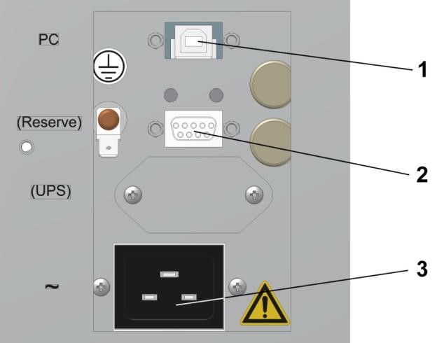
Figure 5-22: EA Electrical Connections
Legend:
- "PC" PC connector (USB)
- "Reserve" reserve
- "~" mains connector
Proceed as follows:
- Connect the PC to the appropriate connector (1) on the back of the analyzer using the correct cable.
- Connect the power supply cable to the mains connector (3).
- If you wish, connect a printer to the PC.
- If you wish, connect a balance to the PC.
Configuring the balance
The serial interface parameters of a connected balance must match the parameters of the PC's serial interface. If you have not entered anything different, the operating software configuration file sets the PC's serial interface as follows:
- Baud: 2400
- Data bits: 7
- Stop bits: 1
- Parity: odd
Select Options > Configuration to edit the parameters of the PC's serial interface if your balance requires different settings.
Connecting Supply / Waste Lines
The following section is part of initial start-up. All steps described in initial startup before connecting supply lines and waste gas lines must have already been performed.
Detail of the rear
The following picture shows a detail of the rear of the analyzer with the corresponding gas connections:
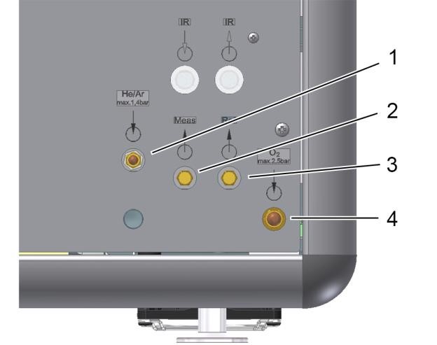
Figure 5-23: EA Gas Connections
Legend:
- "He" carrier gas inlet
- "Meas" measuring gas outlet
- "Ref" reference gas outlet (from TCD)
- "O2" oxygen inlet
Connecting supply lines
Proceed as follows:
- Connect the carrier gas supply line to the carrier gas inlet (1).
- Connect the oxygen supply line to the oxygen gas inlet (4).
Connecting to isoprime precisION IRMS
The measuring gas output from the EA 'measuring gas outlet' must be connected to the input 'EA inlet' of the isoprime precisION IRMS. This allows for sample transfer from the EA to the IRMS via the centrION.
centrION Rear Panel (Mid option)
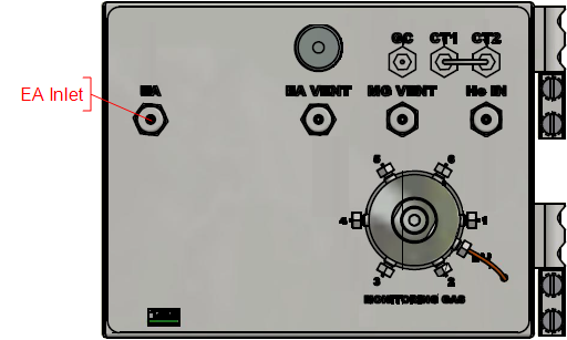
Figure 5-24: EA Sample In
EA dilution and expected sample
For correct EA sample dilution the expected sample flow must be accurate. It is dependent upon the sample pressure applied to the EA. Too high pressure will cause the EA baseline to rise and can indeed stop the helium flow through the TCD. Too low pressure will reduce the amount of sample incident on the MS and thus reduce the sensitivity.
If the system is to be re-tuned then the expected sample flow should be remeasured and inputted in the advanced window of the centrION inlet and dilution. Please contact Elementar if you wish to alter or suspect a problem with the setup.
Switching ON
The following section is part of initial start-up. All steps described in initial startup before switching on must have already been performed.
Proceed as follows:
- If not done so far, plug the power supply plugs of the analyzer and the peripherals into the sockets.
- Turn on PC, monitor and printer. Wait until the boot process is completed.
- Install the operating software if you have not already done so.
- Switch the main instrument switch on. The instrument performs an initialization routine as well as a reference run of the ball valve and the sample carousel. Wait until this process is complete.
- You have now switched on the instrument.
Default instrument settings
The default gas pressure and mass flow settings are listed below. The settings require the analyzer to be leak-free.
Oxygen intake pressure
Oxygen intake pressure is set to 2.5 bar at the delivery point.
Intake pressure carrier gas
The carrier gas intake pressure is set at the delivery point so that the following values are displayed on screen:
- The "Pressure" displays shows 1200–1250mbar.
- The "MFC-TCD" display shows approx. 200 ml/min.
- The "Flow He / Ar" display shows approx. 200 ml/min.
Flow rate
The following flow rate settings are typical:
- The "MFC-TCD" display shows approx. 200 ml/min for the measuring gas outlet.
- The values for the reference gas outlet are between 30ml/min and 60ml/min. There is no display for the reference gas outlet.
Heating up the furnace / checking parameters
Note the following:
- The following section is part of initial start-up. All steps described in initial start-up before "Heating up the furnaces / checking parameters" must have already been performed.
- Some instrument parameters can not only be defined in the "Device parameters" dialog but also via a method. The following general rule applies:
- If not otherwise defined by a method, the settings in the "Instrument parameters" dialog apply.
- If a parameter is defined differently in the method and in the "Device parameters" dialog, the method takes priority if it is used for the measurement.
Heating up the furnace / checking parameters
Proceed as follows:
- Open the "Device parameters" dialog in the operating software by selecting Options > Settings > Parameters.
- Check furnace working temperatures in the "Temperatures" selection and change them if necessary. See Setting mode-dependent instrument parameters.
- Check the other parameters in the "Temperatures" and "Times" selection and change them if necessary.
- Click OK to confirm your settings. The settings are applied.
Further information about the factory-set parameters can be found under Setting device parameters.
Adjusting Oxygen Dosing
The following section is part of initial start-up. All steps described in initial startup before "Adjusting oxygen dosing" must have already been performed.
Adjusting oxygen dosing
Proceed as follows:
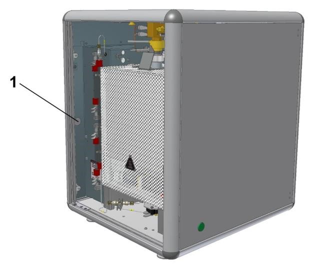
- Open the front door.
-
Push the left side door open from inside (magnetic lock (1)).
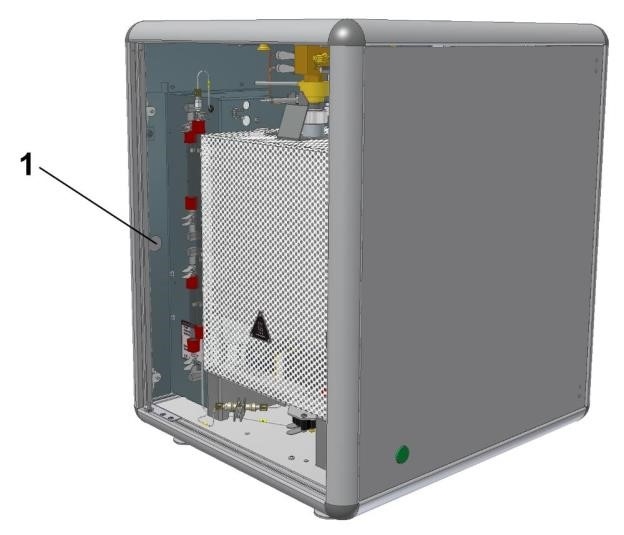
Figure 5-25: ISOTOPE select with side door open
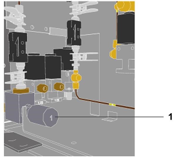
-
The needle valve (1) is now accessible.
- Start oxygen dosing. Execute the Options > Diagnostics > System Test command.
- Activate the "Valves" tab of the "System test" dialog. Switch on the oxygen dosing valve "Valve 4" using the green switch. The bulb behinds it lights up when the valve is switched on.
- Set the needle valve (1) so that the O2 flow meter "Flow O2" displays 28-30 ml/min on screen.
Only leave the oxygen dosing valve on briefly, otherwise the reduction tube filling will be used up.
You have now adjusted oxygen dosing.
- Switch off the oxygen dosing valve "Valve 4" using the red switch. The bulb behind it goes off.
- Close the dialog.
- Close the left side door.
- Close the front door.
Shutting down the instrument
isoprime precisION shutdown protection
If the EA is to be shutdown or serviced (replace parts) then the isoprime precisION must be protected from the reduced helium flow to prevent the filament and pumping system from potentially being damaged. There are two methods to protect the system:
-
Isolation: Seals the system from external factors
Set the Nupro Valve to CLOSED by manually turning the handle clock-wise
or
Set the SIV to ALL OFF (you can set the SIV to waste if it is a short term shutdown).
-
Additional helium flow: Acts as the carrier flow from the EA
Set the sample dilution to 50ml/min.
Both methods are valid, but if the helium supply is to be completely turned off then the full isolation method should be enacted.
What are short measuring breaks?
Short measuring breaks are breaks that last overnight or for 2-5 days.
Procedure
The analyzer and the PC stay online during short measuring breaks. Only the sleep function is activated for the instrument.
Setting the analyzer sleep function.
Proceed as follows:
- Open the "Sleep / wake-up functions" dialog in the operating software by selecting Options > Settings > Sleep / Wake-up.
- Define when to enable the sleep function. Select one of the following options:
- Sleep now... (button): The instrument is shut down immediately.
- "Sleep after end of sample": The instrument is shut down after finishing the last sample.
- "Sleep at sample No.:": The instrument is shut down prior to the appropriate sample.
- Check "Shut off carrier gas".
- Check "Reduce furnace 1 temp" and enter the desired temperature in the box next to "Reduce furnace 1 temp".
- Check "Reduce furnace 2 temp" and enter the desired temperature in the box next to "Reduce furnace 2 temp".
- Specify when to "wake up" the instrument again. The working temperatures are increased again and the instrument is flushed with gas. Choose one of the following options:
- Enter "Date" and "Time" when to "wake up" the instrument and select the box next to "One-time wake-up at above time / date".
- Enter a "Time", select the box next to "Daily wake-up at above time, except:" and select the weekdays on which you do not want to wake up the instrument.
- If you shut down the instrument in the middle of a series, you can continue this series after "wake-up". To do so, check "Continue after wake-up if there are samples".
- Click OK to close the window and save your settings. The instrument is shut down and woken up again according to your settings.
Long Break
What are long measuring breaks?
Long measuring breaks are breaks that last longer than 5 days.
Preparing the instrument for long measuring breaks.
Please observe the following instruction:
Lack of ventilation of the analyzer!
A lack of ventilation leads to overheating of the analyzer. Before you switch off the instrument:
- Set the setpoint temperatures of the furnaces to 0 °C. To do so execute the command Options > Settings > Parameter > Temperatures
- Allow the furnaces to cool down until the temperature displayed is less than 55 °C
Proceed as follows:
- Set the nominal temperatures of the heater to 0 °C via the software. Open the dialog "Instrument parameters" via Options > Settings > Parameters.
- Wait 2–3 hours until the instrument has cooled down to <55 °C.
- Shut off the gas supply.
- Quit the operating software. Execute the following command: File > Exit.
- Switch off the analyzer and its peripherals.
Disconnect the analyzer from the mains. Disconnect the power supply plug. The instrument is ready for long measuring breaks.