Vacuum System Pumping
Overview
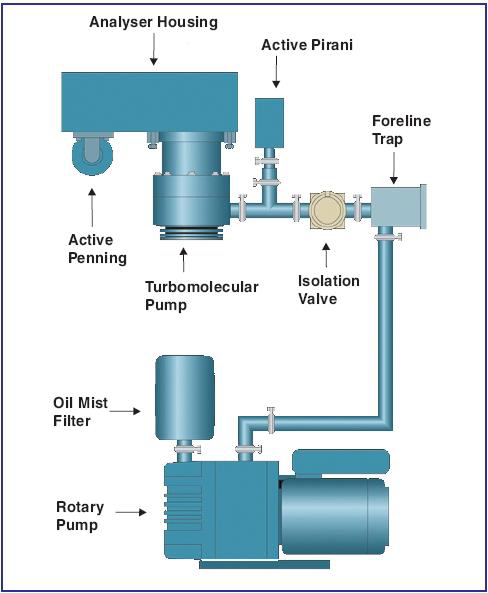
The pumping system produces the high vacuum required for high precision stable isotope analysis and has been designed to provide the high pumping speeds essential for the high gas flow rates required for continuous flow applications.
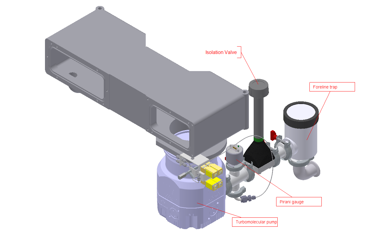
The layout of the pumping system is shown in Figure 4-2 and Figure 4-3 and comprises of a backing pump (e.g. Rotary pump) that provides the backing for a turbo-molecular pump (nEXT240D).
Low vacuum
The rotary pump is connected to the isoprime precisION IRMS by a 2m length of flexible hose, allowing the pump to be conveniently positioned behind and below the instrument. The backing line from the rotary pump is connected to a Foreline trap filled with activated alumina.
The isolation valve allows the rotary pump to be isolated from the turbo-molecular pump, enabling the rotary pump to remain operational during the venting of the mass spectrometer. This ensures that moisture from the air is not adsorbed onto the Foreline trap, which would prolong pump-down times.
The rotary pump is fitted with an oil mist filter to prevent unwanted emission of pump oil vapour into the atmosphere.
High Vacuum
The high vacuum is provided by the turbomolecular pump. An automatic vent valve is fitted to the pump, which ensures that even under conditions of power failure, the chances of rotary pump oil entering the analyzer are minimized. A filter is fitted to the vent valve to stop unwanted particles entering the vacuum system during the venting process.
The turbo-molecular pump is cooled by fans fitted into the instrument housing. One fan is mounted directly underneath the turbo pump; this fan draws air into the case, cooling the pump. Three fans are mounted on the rear panel which extract warm air from the chassis.
All the components of the turbomolecular pump are controlled by the on-board controller which sends status and diagnostic information to the software (IonOS). The power for the pump is supplied by the main power supply unit (MPSU).
Pirani Gauge
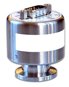
A MicroPirani Vacuum Transducer (Figure 4-4) is used to measure the pressure in the analyzer pumping backing line. This gauge is located adjacent to the turbo pump roughing port and continuously measures the vacuum whenever the electronics unit is powered.
Ionization Gauge
A Cold-Cathode Vacuum Transducer (Figure 4-5) is fitted to the ion optics housing to monitor the pressure inside the analyzer. The gauge is mounted beneath the housing at the collector end.
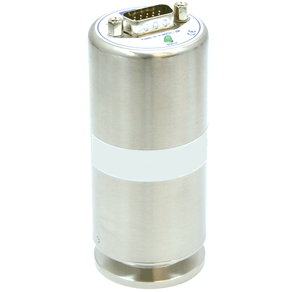
The gauge is enabled as soon as the turbomolecular pump reaches a speed of 60%. Monitoring of the pump speed enables the system to protect the gauge against over-pressure by disabling it when the speed drops below 60%. In normal operation any condition that results in over-pressure will also cause the ion source power supply to be switched off.
Source Inlet Valve
The Source Inlet Valve (SIV) (Figure 4-6), is a device to enable the switching between different inlets. It is connected to the low vacuum line to allow any gases that are not being admitted to the ion source for analysis to be pumped away.
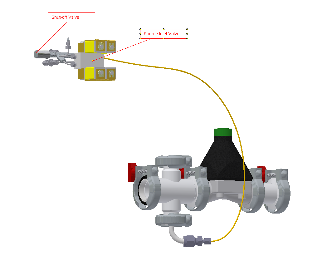
A shut-off valve is provided to isolate this pumping line if it is necessary to carry out maintenance on the SIV without venting the whole system.